KLOUBY

Diagram for JOINTS S-G

Example:
- Power: 0,65 KW
- R.P.M.: 230
- With working angle α 10° Value F=1 we get point P. Torque = 27 Nm corresponding to joint size <> = 25/26 mm. = Types 04S, 04G, 1GB
- With working angle α 30° Value F=0,45 (Kw 0,65 : 0,45 = 1,44 Kw) we get point P1 Torque = 60 Nm corresonding to joint size <> = 32 mm. = Mod. 1S, 1G, 3GB.
Consider that: Torque in Nm = 9550 x Power (KW)
R.P.M.
Torque in Nm = 7020 x Power (HP)
R.P.M.
 Download PDF
Diagram for JOINTS H

Example:
- Power: 5,5 KW
- R.P.M.: 2300
- With working angle α 10° Value F=1 we get point P Torque = 23 Nm corresponding to joint size <> = 28/29 mm. = Types 05H
- With working angle α 25° Value F=0,70 (Kw 5,5 : 0,70 = 7,85 Kw) we get point P1 Torque = 33 Nm corresponding to joint size <> = 32 mm. = Types 1H, 3HB.
Consider that: Torque in Nm = 9550 x Power (KW)
R.P.M.
Mt. in Nm = 7020 x N (HP)
R.P.M.
Instruction for a correct fitting up
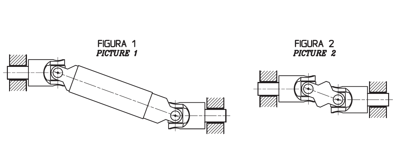
a. To obtain a uniform rotary motion always use either two opposite single joints or one double join. The pillow blocks are to be positioned as close as possible to the joints (see PICTURES 1 and 2).
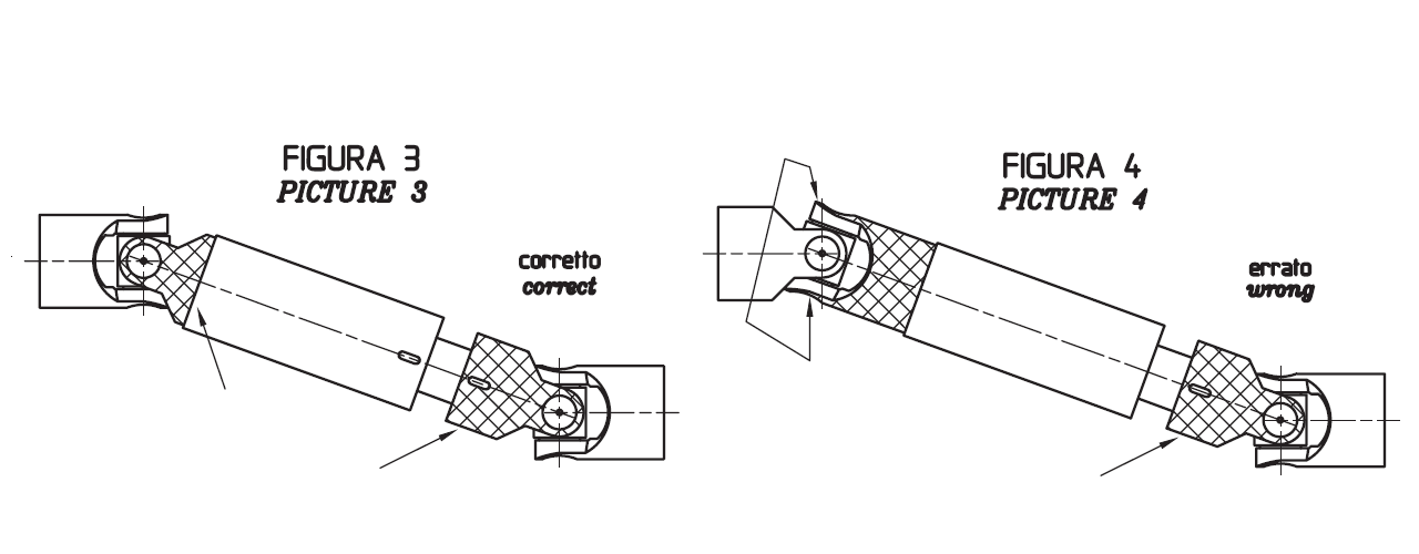
b. When using two opposite single joints respct the allignment of the inside yokes. In extensible transmitions also pay attention than the little lines stamped tally (see PICTURES 3 CORRECT, PICTURE 4 WRONG).
 S - JEDNODUCHÉ KLOUBY
 G - JEDNODUCHÉ KLOUBY KLUZNÉ ULOŽENÍ
 H - JEDNODUCHÉ KLOUBY S JEHLOVÝM ULOŽENÍM
 X - JEDNODUCHÉ NEREZOVÉ KLOUBY S KLUZNÝM ULOŽENÍM
Potřebujete poradit?

Novinky
20.03.2024
Kuželové převodovky v provedení EX
Úhlové převodovky s certifikátem ATEX do explozivního prostředí ➡️ SPLNĚNO ✅ Naši italští kolegové z firmy Unimec S.p.A. si ve vývoji mákli a tak může...
číst celé